Laser Engraving Photo Settings: Power, Speed and Line Interval
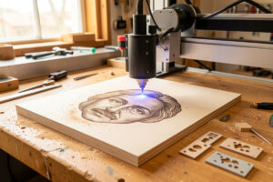
The core starting points for laser photo engraving are a 0.1 mm line interval (254 DPI), a dithered image on a diode or grayscale on a CO2, and a speed-and-power pair you confirm on a test grid. On my 40W-class diode burning maple, that lands near 100 mm/s at 18–22% power with air assist on. Every one of those numbers is a starting point, not a recipe — the material decides the final value.
This is the settings deep-dive for the complete photo engraving guide. I want you to leave understanding what each setting actually does to the burn, because once you know that, you can dial any new material yourself instead of hunting forum threads for a magic number that was tuned on someone else’s machine, lens, and wood lot.
The four settings that matter, in order
Photo quality rides on four levers: line interval (DPI), speed, power, and dithering mode. In my experience their impact order is interval first, then the speed-power balance, then mode. Get the interval wrong and no amount of power tuning saves the image; get it right and you have a wide, forgiving window for the rest. Focus sits underneath all four — it is not a “setting” you type, but a soft focus ruins every number above it.
Line interval and DPI: the resolution lever
Line interval is the gap between scan lines; DPI is the same thing expressed as dots per inch. For most diode photo work I run 0.1 mm interval, which is 254 DPI, and it is the sweet spot for a reason. Coarser than about 0.13 mm (roughly 195 DPI) and the lines visibly separate, leaving a striped, empty look. Finer than 0.08 mm (about 318 DPI) and the burns overlap, shadows smear into solid black, highlights vanish, and run time balloons for no extra real detail.
The trap is thinking finer is always sharper. It is not, because your dot size sets the real resolution ceiling. A diode laying down 0.1 mm dots cannot resolve detail finer than 0.1 mm no matter how tight you set the interval — past that point you are just stacking heat. Match the interval to the dot size your machine actually produces, which a test card reveals immediately.
| Line interval | DPI | Result | Use when |
|---|---|---|---|
| 0.13 mm | ~195 | Visible lines, faster | Large pieces, coarse art, draft preview |
| 0.1 mm | 254 | Sweet spot for diode photos | Most wood and leather portraits |
| 0.08 mm | ~318 | Fine, slower, risk of overlap | Slate, tile, fiber on metal |
| 0.06 mm | ~423 | Very fine, heavy overlap risk | Small high-detail tile or metal only |
Speed and power: the tone balance
Speed and power together set how much energy each spot receives, and they trade off. Slowing down or raising power both deepen the burn; the art is finding a pair that makes shadows read fully dark while highlights stay clean and unburned. My approach is to fix a sensible speed, then sweep power on a grid, because on most diode wood I find the speed window is wider than the power window.
On the xTool S1 diode into maple, I start around 100 mm/s and sweep power from roughly 12% to 28%, looking for the cell where the darkest shadow is genuinely black but the brightest highlight is still bare wood. On the OMTech Polar 350 CO2 doing slate, I run faster — near 300 mm/s — at modest power, because slate frosts with surprisingly little energy and over-driving it just chips the surface. Treat both numbers as my bench’s starting point and verify on yours.
Dithering versus grayscale mode
Mode is how the machine fakes continuous tone. On a diode, dithering is the answer because the diode is essentially on/off and cannot hold smooth power ramps — error-diffusion dithers such as Jarvis and Stucki give natural-looking photo tone, Atkinson gives a punchier high-contrast look. On a CO2 or fiber that modulates power cleanly, grayscale opens up genuinely smooth gradients. I cover the whole decision in grayscale vs dithering, and the eight specific LightBurn dither algorithms in the algorithm comparison.
Scan angle, dot size, and bidirectional scanning
Two smaller settings still move the needle. Scan angle rotates the engraving direction; on wood I sometimes shift to 45° so the scan lines do not run parallel with a strong grain line, which keeps the grain from masquerading as image detail. Dot size, in LightBurn’s grayscale dot mode, sets how big each modulated dot lands — too large and detail clumps, too small and the image goes faint.
Bidirectional (back-and-forth) scanning is faster and fine for most photos, but if you see a slight zig-zag offset between alternating lines, your machine needs a scan-offset adjustment or you should drop to unidirectional for that job. On a sharp, high-DPI portrait that offset shows up as a faint double-edge, so it is worth a glance on your test card.
Focus: the setting you cannot type
Focus is underneath every number above. A photo run a millimetre out of focus comes out soft and grey even with perfect power and speed, because the beam spot widens and the dots lose their edges. I set focus with the focus tool or a ramp test on every job — never by eye. If your machine has a fixed focal length, use the spacer or autofocus rather than trusting the last job’s height, especially when material thickness changes between a 3 mm tile and a 19 mm board.
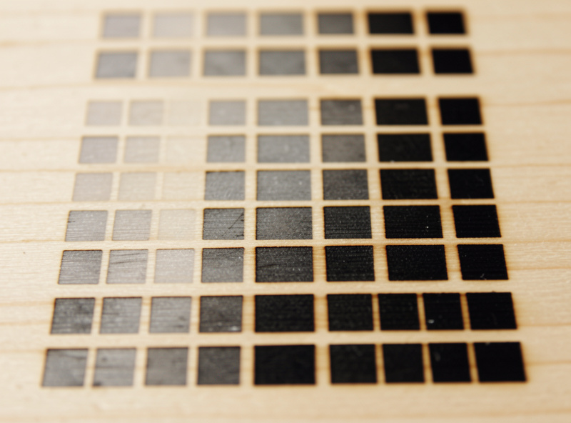
The test card is the real setting
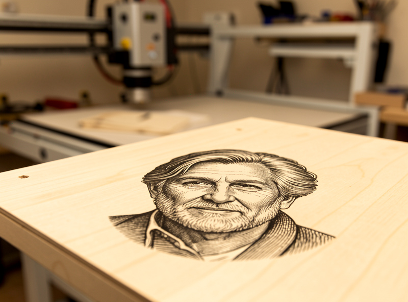
None of these numbers count until you have proven them on the actual material lot. For photos I burn LightBurn’s image test, which tiles the same small portrait across a grid of stepped speed and power, then I read it under good light for the cell where shadows are black, highlights are clean, and the face has depth. That winning cell is the only setting I trust, and I log it per material so the next batch starts from data, not guesswork. New lot of wood, new box of tile, new lens after a cleaning — any of those can shift the answer, so the card is non-negotiable.
Frequently Asked Questions
What DPI is best for laser engraving photos?
For most diode wood photos, 254 DPI (a 0.1 mm line interval) is the sweet spot. Slate, tile, and fiber metal work can go finer to about 318 DPI. Going past your machine’s dot size adds heat and run time without adding real detail.
What speed and power should I use for photo engraving on a diode?
A common starting point on a 40W-class diode into maple is around 100 mm/s and 18 to 22 percent power with air assist on. Sweep power on a test grid to find the cell where shadows read black and highlights stay clean.
Why does my photo look striped or lined?
Your line interval is too coarse, so the scan lines separate visibly. Drop to 0.1 mm (254 DPI) for diode photos. If lines still show, check for a bidirectional scan offset that needs adjustment or switch to unidirectional.
Should I change the scan angle for photo engraving?
Sometimes. On strongly grained wood, rotating the scan angle to 45 degrees keeps the scan lines from running parallel with the grain, which otherwise reads as fake image detail. On most other materials the default angle is fine.
Does power or speed matter more for photo contrast?
They work together to set energy per spot, but on most diode wood the speed window is wider than the power window. Fix a sensible speed first, then sweep power to dial in the shadow depth without scorching highlights.
How do I keep highlights from burning?
Lower power or raise speed so bright areas receive little energy, prep the image so true whites map to bare material, and confirm focus. Highlights burning usually means too much energy overall or an image with no real white point.